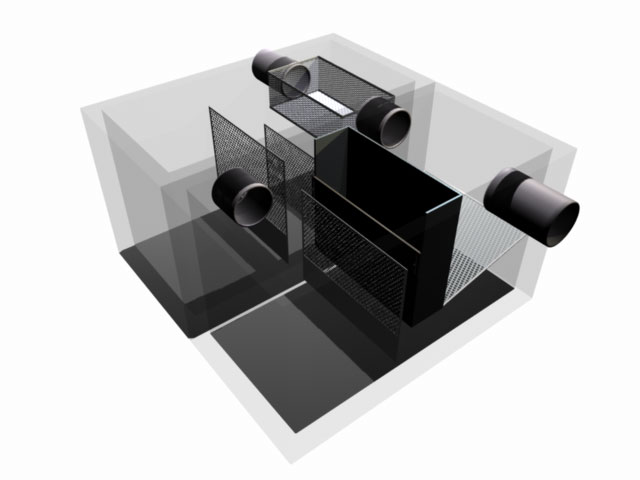
Piped Internal Bypass vault systems are based on twin vault systems, but are limited to parallel vault arrangements. The bypass vault system adds a “relief” or bypass pipe located above the normal connector pipe and outlet pipe, so that additional flows can be accommodated. These systems are used when flows from off site add to the total flow volume of a design, but not to the water quality flow. We also manufacture Intergral Internal Bypass Systems which feature our “periscope” type bypass. This type of bypass is also used in the CrystalCombo Hybrid Polisher Systems.
In bypass vault systems, the trash screening basket and two out of three baffles are in the front vault. All flows, including bypass, pass through the trash screening basket. A third baffle, the spill protection reservoir,and the coconut fiber filter are in the second vault. Normal flows enter the device from the endwall, top, or one side wall of the front vault, pass through the treatment elements in that vault, and then cross over to the second vault via a connector pipe. Normal flows then pass through the remaining elements in the second vault, and exit out the back of that vault through the endwall, or either side wall. When flows reach a predetermined design level, the device will begin to bypass. Most of the flow will still pass through all treatment elements, but some flow will pass through the trash screening basket, through both vaults that act as sediment traps, and out of the device. The position of the bypass pipe (above the connector pipe) assures that the full treatment flow will always be higher than the bypass flow. For these systems, two vaults must be parallel as shown in the sketch above. There are other possibilities when special circumstances dictate, but they are not as cost efficient. The capacities of our twin vault bypass devices are shown below. The capacities will change, based on the position of the bypass pipe, and the hydraulic gradient in your pipe system. In some areas, other sizes may be available.
| Model | Vault Dimensions (H x W x L) | Total Flow Path | Maximum Flow |
|---|---|---|---|
| 1246 IB | 6' x 4' x 6' | 12' | 17 cfs |
| 1856 IB | 9' x 5' x 6' | 18' | 32 cfs |
| 2056 IB | 10' x 5' x 6' | 20' | 35 cfs |
| 2466 IB | 12' x 6' x 6' | 24' | 50 cfs |


